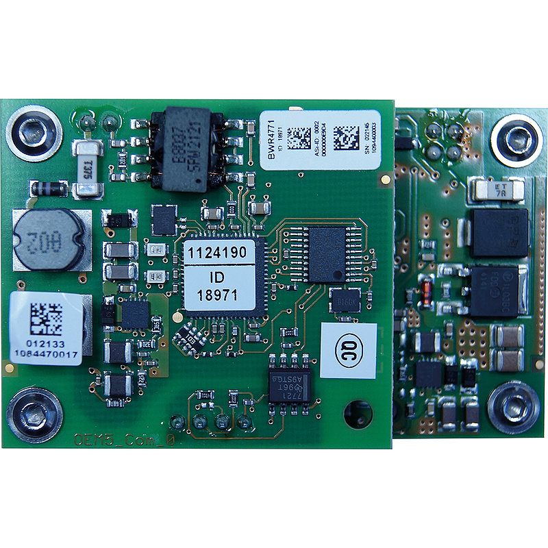
BWR4771ASi-5 PCB Module with integrated IO-Link Master, 65 mm x 40 mm, 4 x IO-Link ports, wiring pins, straight
Product description
ASi-5 PCB module with integrated IO-Link master, 65 mm x 40 mm, 4 x IO-Link ports with configurable conectors for port class A or Port class B (4 x C/Q), 4 x digital inputs/outputs, sensor supply (IO-Link supply and input/output supply) out of AUX, LED, periphery connection via wiring pins, straight, ASi connection via wiring pins, straight, 1 ASi-5 address
Technical data
| Number of IO-Link Ports | 4 |
|
IO-Link Port Class A
Port class A (M12): Pin 4 configurable (IO-Link/DI/DO), additional digital input at pin 2. Compatible with 3 pol IO-Link devices (M8). Configurable conectors: Terminal assignment (C/Q, L+, L-, I) compatible with pin assigment of IO-Link port class A (M12). Connected IO-Link devices with port class B (M12) with a higher current consumption have to be supplied directly via a separate power supply. Compatible with 3 pol IO-Link devices (M8). | configurable conectors |
|
IO-Link Port Class B
Port class B (M12): Pin 4 configurable (IO-Link/DI/DO), additional power supply (galvanically isolated) for IO-Link devices at pins 2 and 5. Compatible with 3 pol IO-Link devices (M8). Configurable conectors: Terminal assignment (C/Q, L+, L-, I) compatible with pin assigment of IO-Link port class A (M12). Connected IO-Link devices with port class B (M12) with a higher current consumption have to be supplied directly via a separate power supply. Compatible with 3 pol IO-Link devices (M8). | configurable conectors |
|
Inputs/outputs
In addition to connecting IO-Link devices (Class A and/or Class B) to the ASi modules with integrated IO-Link masters, it is possible to process additional digital and/or analog I/O signals, depending on the design and configuration. C/Q (configurable IO-Link ports): The C/Q connections (pin 4) of the IO-Link masters Class A and Class B can optionally be configured for IO-Link communication, as digital inputs or as digital outputs. I/O (self-configuring digital inputs/outputs): The I/O connections (pin 2) of the IO-Link masters Class A are self-configuring connections that can optionally be used as additional digital inputs and/or digital outputs. I (digital inputs): The I connections (pin 2) of the IO-Link masters Class A can be used as additional digital inputs. AI (analog inputs): The I Sig+/24V connections of the IO-Link master Class A can be used as additional analog inputs (e.g. 4 ... 20 mA). | 4 x C/Q + 4 x I/O |
|
Sensor supply (IO-Link supply and input/output supply)
IO-Link and additional inputs/outputs are supplied by ASi or by AUX (auxiliary 24 V power). If supplied by ASi, inputs can neither be connected to earth nor to external potential. | out of AUX |
|
Actuator supply (for IO-Link ports class B)
Connection via M12: For IO-Link ports class B the supply of actuators is provided by an additional (galvanically isolated) power supply by AUX (auxiliary 24 V power) via Pin 2 (P24) and Pin 5 (N24). Connection via clamps: If connected IO-Link Devices with IO-Link ports class B need a higher current consumption, additionally they can be supplied directly via the power supply. | out of AUX |
|
Flat design, installation in cable duct possible
Modules with a flat housing design and with cables which exit the sides make these ideal for installation in cable ducts, cable channels, cable troughs, cable rails or cable trays. Please note the respective housing depth for your particular installation. | no |
| Connection | wiring pin, straight |
|
ASi connection
The connection to ASi and AUX (24 V auxiliary power) is made for modules in the active distributor or blue IP67 housing via the yellow or black ASi profile cable with piercing technology or via an M12 plug. Modules for the control cabinet are connected via terminals and PCB modules via wiring pins, connection wires or terminals.
| wiring pin, straight |
|
ASi address
Bihl+Wiedemann offers modules with AB address, single address or ASi-5 address. In some cases, ASi modules can occupy several (different) addresses. Mixed operation of modules with different addressing in the same ASi circuit is permitted. | 1 ASi-5 address |
How to get started with Bihl+Wiedemann products
How to easily implement your ASi installation
How to troubleshoot an existing ASi installation
Manuals
EPLAN Macros
Device Description Files (GSD, EDS, ESI, SDD, etc.)
Video Tutorial
- Video Tutorial: Tips & Tricks: Replacing a defective device (DE)
- Video Tutorial: Tips & Tricks: Replacing a defective device (EN)
- Video Tutorial: Tips & Tricks in ASIMON360: Online bus information (DE)
- Video Tutorial: Tips & Tricks in ASIMON360: Online bus information (EN)
- Video Tutorial: Tips & Tricks in ASIMON360: Custom catalog (DE)
- Video Tutorial: Tips & Tricks in ASIMON360: Custom catalog (EN)
- Video Tutorial: Tips & Tricks in ASIMON360: How to copy slaves and devices (DE)
- Video Tutorial: Tips & Tricks in ASIMON360: How to copy slaves and devices (EN)
- Video Tutorial: Tips & Tricks in ASIMON360: How to deactivate slaves (DE)
- Video Tutorial: Tips & Tricks in ASIMON360: How to deactivate slaves (EN)
- Video Tutorial: ASi Control Tools360: Configuration of ASi-5 devices (DE)
- Video Tutorial: ASi Control Tools360: Configuration of ASi-5 devices (EN)
- Video Tutorial: ASi Control Tools360: First Steps (DE)
- Video Tutorial: ASi Control Tools360: First Steps (EN)
Quick Start Guides
- Quick Start Guide: Tips & Tricks: Replacing a defective device (DE)
- Quick Start Guide: Tips & Tricks: Replacing a defective device (EN)
- Quick Start Guide: Tips & Tricks in ASIMON360: Custom catalog (DE)
- Quick Start Guide: Tips & Tricks in ASIMON360: Custom catalog (EN)
- Quick Start Guide: Tips & Tricks in ASIMON360: How to copy slaves and devices (DE)
- Quick Start Guide: Tips & Tricks in ASIMON360: How to copy slaves and devices (EN)
- Quick Start Guide: Tips & Tricks in ASIMON360: How to deactivate ASi modules (DE)
- Quick Start Guide: Tips & Tricks in ASIMON360: How to deactivate ASi modules (EN)
- Quick Start Guide: Tips & Tricks in ASIMON360: Online bus information (DE)
- Quick Start Guide: Tips & Tricks in ASIMON360: Online bus information (EN)
- Quick Start Guide: ASi Control Tools360 – First steps (DE)
- Quick Start Guide: ASi Control Tools360 – First steps (EN)
- Quick Start Guide: Configuration of ASi-5 devices (DE)
- Quick Start Guide: Configuration of ASi-5 devices (EN)
- Quick Start Guide: Configuration of ASi-5 devices (PL)
