Archives Safety I/O Modules
Archives Safety I/O Modules: Input/output modules
| Figure | Type | Housing | "IP20": "IP40": Protected against solid foreign bodies having a diameter of 1.0 mm or larger, protected against access with a wire, no protection against water. "IP54": Protection against dust in damaging amounts, complete protection against contact, protection against splashing water in any angle.
Dust-tight, full protection against contact, protection against temporary immersion. | Safe inputs can be configured as 1-channel or 2-channels depending on the desired application or PL and SIL level. | An externally connected relay (contactor) can be monitored by connecting the feedback loop to the EDM input. | Outputs Safety, SIL 3, cat. 4 | Outputs digital | Safety signal inputs | inputs are supplied by ASi or by AUX (24 V or 48 V auxiliary power). If supplied by ASi, inputs shall not be connected to earth or to external potential. | Electronic outputs are supplied by ASi or by AUX (24 V or 48 V auxiliary power). If supplied by ASi, outputs shall not be connected to earth or to external potential.
For relay outputs the relay contacts are initiated from ASi. The load circuit is powered externally as specified in the data sheet. | Length of connector cable | The connection to ASi and AUX (24 V auxiliary power) is made for modules in the active distributor or blue IP67 housing via the yellow or black ASi profile cable with piercing technology or via an M12 plug. Modules for the control cabinet are connected via terminals and PCB modules via wiring pins, connection wires or terminals.
| Bihl+Wiedemann offers modules with AB address, single address or ASi-5 address. In some cases, ASi modules can occupy several (different) addresses. Mixed operation of modules with different addressing in the same ASi circuit is permitted. | Coating protects components and circuit boards when touched. Thick coated and thin coated are available. | Special function | Article No. |
|---|---|---|---|---|---|---|---|---|---|---|---|---|---|---|---|---|
 |
IP20, 22,5 mm x 114 mm, 6 x 4 contacts, Safety
|
22.5 mm x 99.0 mm x 114.5 mm, 6 x 4 contacts
|
IP20
|
8 x 2 channels
|
up to 16, depending on configuration
|
1 release circuit, 1 x electronic safe output
|
no digital outputs
|
OSSDs, complementary OSSDs, complementary switch, floating contacts
|
out of AUX
|
out of AUX
|
unlimited
|
Push-in terminals
|
depending on configuration
|
given by housing
|
no special function
| BWU2578 ASi Safety I/O Module, IP20, 8SI/1SO/16I |
 |
IP20, 22,5 mm x 114 mm, 6 x 4 contacts, Safety
|
22.5 mm x 99.0 mm x 114.5 mm, 6 x 4 contacts
|
IP20
|
4 x 2 channels
|
-
|
2 release circuits, 2 x electronic safe outputs, augmented reliability
|
up to 8 x electronic, depending on configuration
|
OSSDs, complementary OSSDs, complementary switch, floating contacts
|
out of AUX
|
out of AUX
|
unlimited
|
Push-in terminals
|
depending on configuration
|
given by housing
|
no special function
| BWU2314 ASi Safety I/O Module, IP20, 4SI/2SO/8I/8O |
 |
IP20, 22,5 mm x 114 mm, 6 x 4 contacts, Safety
|
22.5 mm x 99.0 mm x 114.5 mm, 6 x 4 contacts
|
IP20
|
4 x 2 channels
|
-
|
2 release circuits, 2 x electronic safe outputs, augmented reliability
|
up to 8 x electronic, depending on configuration
|
OSSDs, complementary OSSDs, complementary switch, floating contacts
|
out of AUX
|
out of AUX
|
unlimited
|
coded clamps
|
depending on configuration
|
given by housing
|
no special function
| BWU3575 ASi Safety I/O Module, IP20, 4SI/2SO/8I/8O |
 |
IP20, 22,5 mm x 114 mm, 6 x 4 contacts, Safety
|
22.5 mm x 99.0 mm x 114.5 mm, 6 x 4 contacts
|
IP20
|
8 x 2 channels
|
up to 16, depending on configuration
|
1 release circuit, 1 x electronic safe output
|
no digital outputs
|
OSSDs, complementary OSSDs, complementary switch, floating contacts
|
out of AUX
|
out of AUX
|
unlimited
|
coded clamps
|
depending on configuration
|
given by housing
|
no special function
| BWU3118 ASi Safety I/O Module, IP20, 8SI/1SO/16I |
 |
IP20, 22,5 mm x 114 mm, 6 x 4 contacts, Safety
|
22.5 mm x 99.0 mm x 114.5 mm, 6 x 4 contacts
|
IP20
|
6 x 2 channels
|
2 EDM
|
2 release circuits, 2 x electronic safe outputs
|
no digital outputs
|
OSSDs, complementary switch, floating contacts
|
out of AUX
|
out of AUX
|
unlimited
|
coded clamps
|
depending on configuration, optimised for ASIMON360
|
given by housing
|
no special function
| BWU3877 ASi Safety I/O Module, IP20, 6SI/2SO/2EDM |
Archives Safety I/O Modules: Safety Circuit Board Modules
| Figure | Type | Circuit board dimensions | Safe inputs can be configured as 1-channel or 2-channels depending on the desired application or PL and SIL level. | Inputs digital | Outputs digital | Outputs Safety, SIL 3, cat. 4 | Safety signal inputs | Connection possible via wiring pins, screw terminals, solder lugs or connecting wires. Further connection options are available on request. | Length of connector cable | Coating protects components and circuit boards when touched. Thick coated and thin coated are available. | "IP20": "IP40": Protected against solid foreign bodies having a diameter of 1.0 mm or larger, protected against access with a wire, no protection against water. "IP54": Protection against dust in damaging amounts, complete protection against contact, protection against splashing water in any angle.
Dust-tight, full protection against contact, protection against temporary immersion. | Display of the status of the inputs/outputs, ASi communication or peripheral errors and the status of the AUX supply according to the ASi specification. | inputs are supplied by ASi or by AUX (24 V or 48 V auxiliary power). If supplied by ASi, inputs shall not be connected to earth or to external potential. | Electronic outputs are supplied by ASi or by AUX (24 V or 48 V auxiliary power). If supplied by ASi, outputs shall not be connected to earth or to external potential.
For relay outputs the relay contacts are initiated from ASi. The load circuit is powered externally as specified in the data sheet. | Bihl+Wiedemann offers modules with AB address, single address or ASi-5 address. In some cases, ASi modules can occupy several (different) addresses. Mixed operation of modules with different addressing in the same ASi circuit is permitted. | Article No. |
|---|---|---|---|---|---|---|---|---|---|---|---|---|---|---|---|---|
 |
circuit board 73 mm x 37,5 mm, Safety
|
73 mm x 37,5 mm
|
1 x 2 channels
|
no digital inputs
|
2 x electronic
|
no local safe output
|
floating contacts
|
wiring pins, angled
|
max. 15 m
|
no
|
IP00
|
yes
|
out of ASi
|
out of AUX
|
1 Single address
| BWR1801 ASi Safety PCB Module, 73 mm x 37,5 mm, 1SI/2O, wiring pins, angled |
|
circuit board 73 mm x 37,5 mm, Safety
|
73 mm x 37,5 mm
|
1 x 2 channels
|
no digital inputs
|
2 x electronic
|
no local safe output
|
floating contacts
|
solder lugs
|
max. 15 m
|
no
|
IP00
|
yes
|
out of ASi
|
out of AUX
|
1 Single address
| BWR1934 ASi Safety PCB Module, 73 mm x 37,5 mm, 1SI/2O, solder lugs |
Archiv Safety Active Distributors
| Figure | Type | Housing | "IP20": "IP40": Protected against solid foreign bodies having a diameter of 1.0 mm or larger, protected against access with a wire, no protection against water. "IP54": Protection against dust in damaging amounts, complete protection against contact, protection against splashing water in any angle.
Dust-tight, full protection against contact, protection against temporary immersion. | Safe inputs can be configured as 1-channel or 2-channels depending on the desired application or PL and SIL level. | An externally connected relay (contactor) can be monitored by connecting the feedback loop to the EDM input. | Outputs Safety, SIL 3, cat. 4 | Outputs digital | Safety signal inputs | inputs are supplied by ASi or by AUX (24 V or 48 V auxiliary power). If supplied by ASi, inputs shall not be connected to earth or to external potential. | Electronic outputs are supplied by ASi or by AUX (24 V or 48 V auxiliary power). If supplied by ASi, outputs shall not be connected to earth or to external potential.
For relay outputs the relay contacts are initiated from ASi. The load circuit is powered externally as specified in the data sheet. | Length of connector cable | The connection to ASi and AUX (24 V auxiliary power) is made for modules in the active distributor or blue IP67 housing via the yellow or black ASi profile cable with piercing technology or via an M12 plug. Modules for the control cabinet are connected via terminals and PCB modules via wiring pins, connection wires or terminals.
| Bihl+Wiedemann offers modules with AB address, single address or ASi-5 address. In some cases, ASi modules can occupy several (different) addresses. Mixed operation of modules with different addressing in the same ASi circuit is permitted. | Coating protects components and circuit boards when touched. Thick coated and thin coated are available. | Special function | Article No. |
|---|---|---|---|---|---|---|---|---|---|---|---|---|---|---|---|---|
 |
Active distributor ASi
|
depth: 35 mm
|
IP67
|
1 x 2 channels
|
no local input
|
-
|
1 x electronic
|
floating contacts
|
out of ASi
|
out of AUX
|
-
|
ASi profile cable
|
1 Single address
|
-
|
to connect Schmerzal AZM161 and Fortress amGardPro to ASi
| BWU4904 Active Distributor ASi Safety, IP67, 1SI/1O |
 |
Active distributor ASi Safety
|
depth: 19 mm
|
IP67
|
1 x 2 channels
|
1
|
no local safe output
|
1 x electronic
|
OSSDs
|
out of AUX
|
out of AUX
|
-
|
ASi profile cable
|
1 Single address
|
given by housing
|
no special function
| BWU3638 Active Distributor ASi Safety, IP67, 1SI/1I/1O |
Archives Speed Monitor
| Figure | Type | Model | "IP20": "IP40": Protected against solid foreign bodies having a diameter of 1.0 mm or larger, protected against access with a wire, no protection against water. "IP54": Protection against dust in damaging amounts, complete protection against contact, protection against splashing water in any angle.
Dust-tight, full protection against contact, protection against temporary immersion. | Safe Monitoring | Encoder signal/Sensor signal | Outputs Safety, SIL 3, cat. 4 | Number of monitored axes | Encoder/Sensor connection | Access to ASi master and safety monitor via own software from Bihl+Wiedemann using the diagnostic interface (e.g. USB, RJ45, RS232). For certain devices with Ethernet-based fieldbus (PROFINET, EtherNet/IP), there is also the option of diagnostics and configuration directly via the fieldbus interface.
The latest version of the device description file of the gateway/gateway with integrated safety monitor (GSD, GSDML, EDS, etc.) is available in the "Downloads" section of the respective device. | The connection to ASi and AUX (24 V auxiliary power) is made for modules in the active distributor or blue IP67 housing via the yellow or black ASi profile cable with piercing technology or via an M12 plug. Modules for the control cabinet are connected via terminals and PCB modules via wiring pins, connection wires or terminals.
| Bihl+Wiedemann offers modules with AB address, single address or ASi-5 address. In some cases, ASi modules can occupy several (different) addresses. Mixed operation of modules with different addressing in the same ASi circuit is permitted. | Article No. |
|---|---|---|---|---|---|---|---|---|---|---|---|---|
 |
Speed Monitor Standalone
|
Speed Monitor for encoders
|
IP20
|
speed + position
|
sine/cosine, TTL, SSI
|
2 release circuits, 2 x electronic safe outputs
|
up to 2 independent axes
|
RJ45
|
USB
|
-
|
-
| BWU3269 Speed Monitor Standalone for 2 encoders, sin/cos, TTL, SSI |
|
Speed Monitor Standalone
|
Speed Monitor for encoders
|
IP20
|
speed + position
|
sine/cosine, TTL
|
2 release circuits, 2 x electronic safe outputs
|
1 axis
|
RJ45
|
USB
|
-
|
-
| BWU3277 Speed Monitor Standalone for 1 encoder, sin/cos, TTL |
 |
-
|
-
|
-
|
-
|
-
|
-
|
-
|
-
|
-
|
-
|
-
| BW2538 Speed Monitor head unit and Speed Monitor sine/cosine for 2 axis |
 |
Speed Monitor Modular
|
Speed Monitor for encoders
|
IP20
|
speed + position
|
sine/cosine, TTL
|
2 release circuits, 2 x electronic safe outputs
|
1 axis
|
RJ45
|
via ASi
|
Push-in terminals
|
depending on configuration
| BWU2868 ASi Speed Monitor Modular for 1 encoder, sin/cos, TTL |
Archives cable adapter for speed monitor
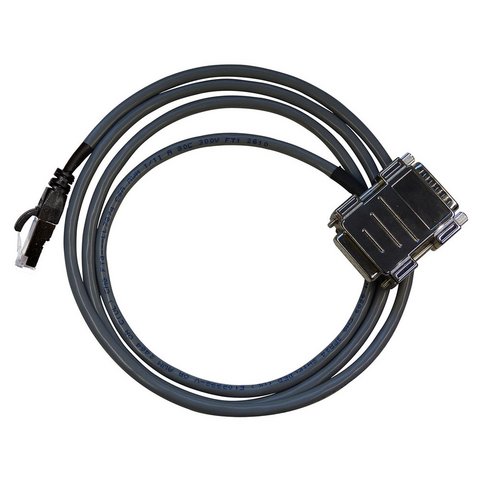
BW3562D-Sub cable adapter for Rockwell KINETIX6000, 15 poles
D-Sub cable adapter 15 poles to RJ45 with 2,5 m connector cable, soldered, for Rockwell KINETIX6000