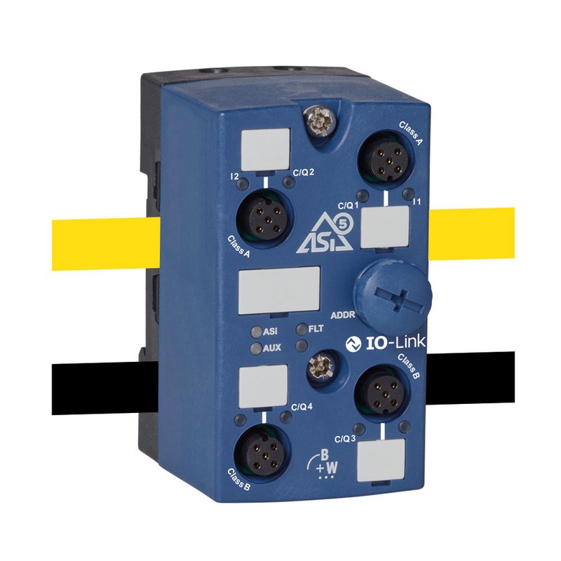
BWU3821ASi-5 Module/IO-Link Master with 4 Ports, IP67, M12, 2 IO-Link ports class A/2I/2 IO-Link ports class B

- Cost-savings through reduced cabling
- Quadruple IO-Link master
- 2 x IO-Link ports class A
- 2 x IO-Link ports class B
Product description
ASi-5 Module/IO-Link Master in IP67, with 4 x M12 sockets, 2 IO-Link ports and 2 digital inputs, IO-Link class A, 2 IO-Link ports, IO-Link class B, input voltage/sensor supply out of AUX, output voltage out of ASi, actuator supply out of AUX, periphery connection via 4 x M12 sockets, 5 poles, ASi connection via profile cable and piercing technology, 1 ASi-5 address.
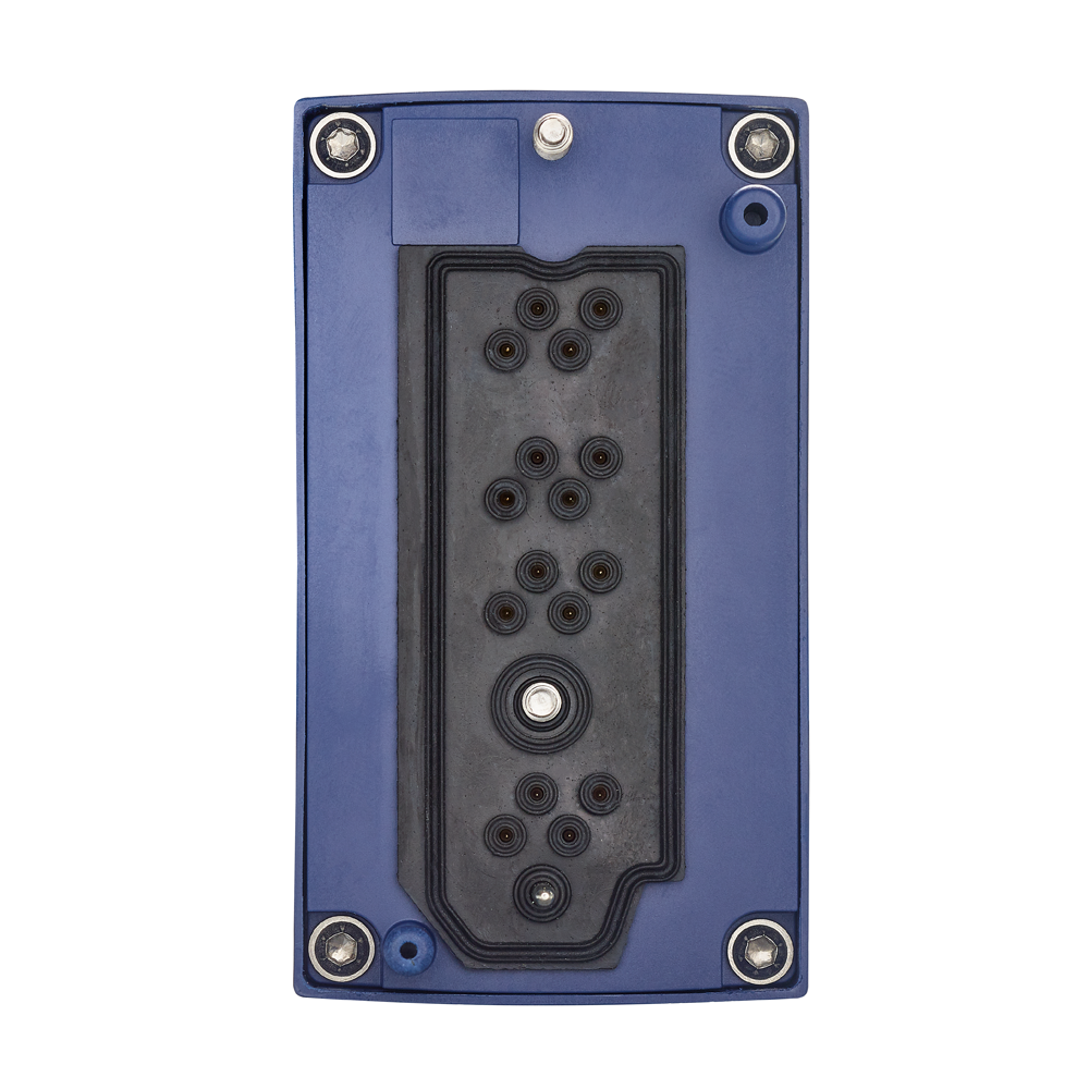
The substructure module is not included in the scope of delivery.
Technical data
| Type | IP67, 4 x M12, ASi-5 |
| Model | IO-Link master |
|
Configurable I/O‘s
Port class A: In this type, Pin 2 is assigned with an additional digital input. Port class B: This type provides additional supply voltage and is suitable for the connection of devices that have an increased power demand. In this case, pins 2 and 5 are used to provide additional (galvanically isolated) supply voltage. Configurability: The C/Q connections may be used for IO-Link configuration or as digital input/output signal. | 2 x IO-Link ports class A + 2 x IO-Link ports class B |
|
Sensor supply (IO-Link supply and input/output supply)
IO-Link and additional inputs/outputs are supplied by ASi or by AUX (auxiliary 24 V power). If supplied by ASi, inputs can neither be connected to earth nor to external potential. | out of ASi |
|
Actuator supply (for IO-Link ports class B)
Connection via M12: For IO-Link ports class B the supply of actuators is provided by an additional (galvanically isolated) power supply by AUX (auxiliary 24 V power) via Pin 2 (P24) and Pin 5 (N24). Connection via clamps: If connected IO-Link Devices with IO-Link ports class B need a higher current consumption, additionally they can be supplied directly via the power supply. | out of AUX |
|
M8/M12 wiring
Single wiring: 1 input or output per connection.
Y wiring: 2 inputs or outputs per connection.
Mixed wiring: 1 input and 1 output per connection.
Exact pin assignment see data sheet. | IO-Link Port Class A + Class B |
|
IO-Link data rate
COM1 = 4.8 kBaud COM2 = 38.4 kBaud COM3 = 230.4 kBaud (optional according to Specification V1.0)
An IO-Link device supports only one of the defined data transmission rates. According to Specification V1.1, the IO-Link master supports all data transmission rates and adapts itself automatically to the data transmission rate supported by the device. | COM1 / COM2 / COM3 |
| IO-Link specification | V1.1 |
| Connection | 4 x M12 sockets, 5 poles |
|
ASi connection
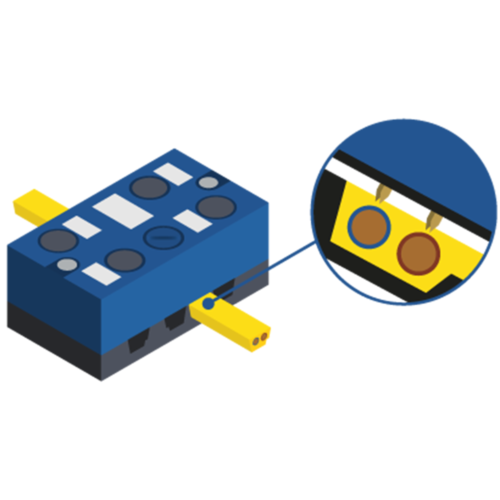
The connection to ASi and AUX (24 V auxiliary power) is made for modules in the active distributor or blue IP67 housing via the yellow or black ASi profile cable with piercing technology or via an M12 plug. Modules for the control cabinet are connected via terminals and PCB modules via wiring pins, connection wires or terminals.
| ASi profile cable |
|
ASi address
Bihl+Wiedemann offers modules with AB address, single address or ASi-5 address. In some cases, ASi modules can occupy several (different) addresses. Mixed operation of modules with different addressing in the same ASi circuit is permitted. | 1 ASi-5 address |
How to get started with Bihl+Wiedemann products
How to easily implement your ASi installation
How to troubleshoot an existing ASi installation
Manuals
Video Tutorial
- Video Tutorial: Tips & Tricks: Replacing a defective device (DE)
- Video Tutorial: Tips & Tricks: Replacing a defective device (EN)
- Video Tutorial: ASIMON360 configuration for IO-Link (DE)
- Video Tutorial: ASIMON360 configuration for IO-Link (EN)
- Video Tutorial: ASi Control Tools360: Configuration of ASi-5 devices (DE)
- Video Tutorial: ASi Control Tools360: Configuration of ASi-5 devices (EN)
