BWU1647Cylindrical ASi Actuator 1I/3O
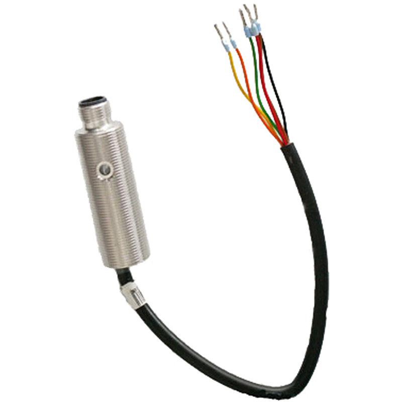
Product description
AB address (up to 62 addresses)
Technical data
| Type | Cylindrical ASi Actuator in stainless steel |
|
ASi-5/ASi-3
The device communicates via the standard ASi-3 and/or ASi-5. | ASi-3 compatible |
| Housing | M18 sleeve in stainless steel, 55 mm |
|
Protection rating
"IP20": "IP40": Protected against solid foreign bodies having a diameter of 1.0 mm or larger, protected against access with a wire, no protection against water. "IP54": Protection against dust in damaging amounts, complete protection against contact, protection against splashing water in any angle.
Dust-tight, full protection against contact, protection against temporary immersion. | IP67 |
|
Line protection fuse
"yes": In the motor module UL approved fuses are placed before each of the motor supply connections. A short circuit in the motor causes this fuse to blow, protecting the connection cable between the module and motor. After blowing the not exchangeable fuse the module is no longer functional and the module needs to be replaced. The characteristics of the fuse must be checked against the motor data before using the module. The protection circuit in the module allows a very simple protection of the motor cables. The fuse for the cable protection is a slow-blow one; without short circuit the robust behavior of the module remains.
The motor module is designed to supply the 24 V directly to the motor. At high currents or surges as they occur for example at braking, the module will not be damaged. The cable protection should be realized outside the motor module with additional measures. | no |
| Inputs digital | 1 |
| Outputs digital | 3 x electronic |
|
Input voltage (sensor supply)
inputs are supplied by ASi or by AUX (24 V or 48 V auxiliary power). If supplied by ASi, inputs shall not be connected to earth or to external potential. | out of ASi |
|
Output voltage (actuator supply)
Electronic outputs are supplied by ASi or by AUX (24 V or 48 V auxiliary power). If supplied by ASi, outputs shall not be connected to earth or to external potential.
For relay outputs the relay contacts are initiated from ASi. The load circuit is powered externally as specified in the data sheet. | out of ASi |
| Connection | 1 x round cable/connecting wires |
|
Round cable
Under normal conditions (no bus termination or repeater), the permissible total length of the ASi segment is max. 100 m. The calculation should take into consideration that the length of the connection cable (round cable) for each connected passive distributor must be doubled. In the case of the active distributors (ASi modules) however only the one ASi profile cable is counted. | 0,20 m |
|
ASi connection
The connection to ASi and AUX (24 V auxiliary power) is made for modules in the active distributor or blue IP67 housing via the yellow or black ASi profile cable with piercing technology or via an M12 plug. Modules for the control cabinet are connected via terminals and PCB modules via wiring pins, connection wires or terminals.
| ASi via M12 |
|
Required Master profile
Required profile that the ASi master needs to have in order to connect and operate the module. | M3 .. M4 |
|
ASi node profile
The node profiles allow numerous quickly configurable settings to be made on the module in order to optimally support the connected peripherals in most applications. The easiest way to select the node profiles is via the PC software. If ID1 is in brackets (), this means it is the changeable default value; if ID1 is without brackets, it means it is a fixed, unchangeable value. | S-9.A.E |
|
ASi address
Bihl+Wiedemann offers modules with AB address, single address or ASi-5 address. In some cases, ASi modules can occupy several (different) addresses. Mixed operation of modules with different addressing in the same ASi circuit is permitted. | 1 AB address |
