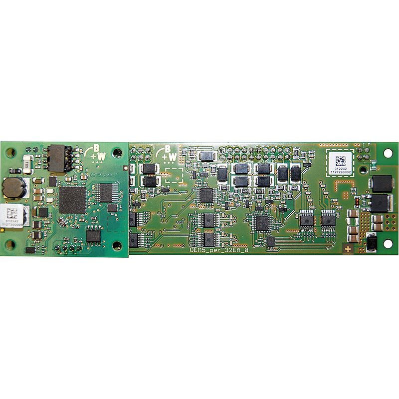
BWR4978ASi-5 PCB Module, 140 mm x 40 mm, self-configuring 32I/O, wiring pins, straight
Product description
ASi-5 PCB Module, 140 mm x 40 mm, up to 32 digital inputs, up to 32 digital outputs, input voltage/sensor supply out of AUX, output voltage/actuator supply out of AUX, max. 350 mA per output, periphery connection via wiring pins, straight, LED, ASi connection via wiring pins, straight, 1 ASi-5 address
Technical data
| Circuit board dimensions | 140 mm x 40 mm |
| Inputs digital | up to 32, depending on configuration |
| Outputs digital | up to 32 x electronic, depending on configuration |
|
Input voltage (sensor supply)
inputs are supplied by ASi or by AUX (24 V or 48 V auxiliary power). If supplied by ASi, inputs shall not be connected to earth or to external potential. | out of AUX |
|
Output voltage (actuator supply)
Electronic outputs are supplied by ASi or by AUX (24 V or 48 V auxiliary power). If supplied by ASi, outputs shall not be connected to earth or to external potential.
For relay outputs the relay contacts are initiated from ASi. The load circuit is powered externally as specified in the data sheet. | out of AUX |
|
PCB connection
Connection possible via wiring pins, screw terminals, solder lugs or connecting wires. Further connection options are available on request. | wiring pins, straight |
|
Coating
Coating protects components and circuit boards when touched. Thick coated and thin coated are available. | no |
|
ASi connection
The connection to ASi and AUX (24 V auxiliary power) is made for modules in the active distributor or blue IP67 housing via the yellow or black ASi profile cable with piercing technology or via an M12 plug. Modules for the control cabinet are connected via terminals and PCB modules via wiring pins, connection wires or terminals.
| wiring pin, straight |
|
ASi address
Bihl+Wiedemann offers modules with AB address, single address or ASi-5 address. In some cases, ASi modules can occupy several (different) addresses. Mixed operation of modules with different addressing in the same ASi circuit is permitted. | 1 ASi-5 address |
How to get started with Bihl+Wiedemann products
How to easily implement your ASi installation
How to troubleshoot an existing ASi installation
Manuals
EPLAN Macros
Device Description Files (GSD, EDS, ESI, SDD, etc.)
Video Tutorial
- Video Tutorial: Tips & Tricks: Replacing a defective device (DE)
- Video Tutorial: Tips & Tricks: Replacing a defective device (EN)
- Video Tutorial: Tips & Tricks in ASIMON360: Online bus information (DE)
- Video Tutorial: Tips & Tricks in ASIMON360: Online bus information (EN)
- Video Tutorial: Tips & Tricks in ASIMON360: Custom catalog (DE)
- Video Tutorial: Tips & Tricks in ASIMON360: Custom catalog (EN)
- Video Tutorial: Tips & Tricks in ASIMON360: How to copy slaves and devices (DE)
- Video Tutorial: Tips & Tricks in ASIMON360: How to copy slaves and devices (EN)
- Video Tutorial: Tips & Tricks in ASIMON360: How to deactivate slaves (DE)
- Video Tutorial: Tips & Tricks in ASIMON360: How to deactivate slaves (EN)
- Video Tutorial: ASi Control Tools360: Configuration of ASi-5 devices (DE)
- Video Tutorial: ASi Control Tools360: Configuration of ASi-5 devices (EN)
Quick Start Guides
- Quick Start Guide: Tips & Tricks: Replacing a defective device (DE)
- Quick Start Guide: Tips & Tricks: Replacing a defective device (EN)
- Quick Start Guide: Tips & Tricks in ASIMON360: Custom catalog (DE)
- Quick Start Guide: Tips & Tricks in ASIMON360: Custom catalog (EN)
- Quick Start Guide: Tips & Tricks in ASIMON360: How to copy slaves and devices (DE)
- Quick Start Guide: Tips & Tricks in ASIMON360: How to copy slaves and devices (EN)
- Quick Start Guide: Tips & Tricks in ASIMON360: How to deactivate ASi modules (DE)
- Quick Start Guide: Tips & Tricks in ASIMON360: How to deactivate ASi modules (EN)
- Quick Start Guide: Tips & Tricks in ASIMON360: Online bus information (DE)
- Quick Start Guide: Tips & Tricks in ASIMON360: Online bus information (EN)
- Quick Start Guide: Configuration of ASi-5 devices (DE)
- Quick Start Guide: Configuration of ASi-5 devices (EN)
- Quick Start Guide: Configuration of ASi-5 devices (PL)
